Thursday, January 17, 2019

Feeding Function of Single-Screw Extrusion


A polymer feed, usually in the form of pellets, drops from the hopper through the feed throat into the rotating screw. This feeding function occurs by gravity in most cases for single-screw extruders. Some feeds, such as sticky powders or recycled film flakes with a large surface to volume ratio, tend to bridge inside the hopper and do not drop freely from the hopper into the screw by gravity. Such non-free flowing feeds require a forced feeding device. A short conical screw installed inside the hopper, called a “crammer feeder”, is widely used for non-free flowing feeds. Single-screw extruders do not require starved-feeding, and they usually operate with a full hopper in a flood-feeding mode. A metered feeding device, such as a volumetric feeder or a loss-in- weight feeder, is used to control the feeding rate and to run the screw in a starved feeding mode in special situations. Many polymers react with oxygen at high temperatures during extrusion, causing undesirable oxidation, degradation, or crosslinking of the molecules. Purging of the feed at the feed throat by an inert gas like nitrogen may be necessary, especially when the screw is run in a starved feeding mode.
The feed throat is directly attached to the heated barrel, and it becomes hot. Feed materials with a low melting point stick to the wall of the feed throat, reducing the feeding rate or completely blocking the feed stream in the worst case. The feed throat must be cooled by water to avoid such feed sticking problem.
A feed stream is often made of several component materials. Even if the component materials are well blended/mixed coming into the hopper, they could segregate inside the hopper. Two different materials with the same shape but different densities, or with the same density but different shapes, readily separate upon flow. “Flow segregation” of the feed materials inside the hopper is a common problem in extrusion.
Because an extruder is a continuous pump without back mixing capability, the first condition for a successful extrusion process is to provide a consistent feeding rate into the screw from the hopper, in terms of both a constant composition and a constant weight. Extrusion problems often arise from an inconsistent feeding rate.
The feeding rate of a polymer feed is determined essentially by the physical characteristics of the feed, such as size and shape, and their distribution, controlling the bulk density (the weight divided by the apparent volume), and the internal friction between the feed constituents. The feeding rate also depends on the inherent properties of the polymer (the solid density, the external friction on the metal surface), the hopper design, and the feed throat design. The external friction of the feed on the hopper wall mainly depends
on the inherent properties of the polymer and the roughness of the hopper wall. A tiny amount of lubricant or additive, especially if it is coated on the surface of the feed, can drastically alter both the internal friction and the external friction.
Because a polymer feed, in pellet, powder, or flake form, becomes interlocked in the hopper, almost supporting its own weight, the pressure at the bottom of the hopper is very low and the feeding rate is usually independent of the amount of feed in the hopper.
The driving force in flood-feeding is gravity. The opposing forces are the centrifugal force exerted by screw rotation and the back-flow of air flowing out of the screw into the hopper through the feed throat. Feed materials contain 30–70% air by volume, and the air is squeezed out of the feed as the feed is compacted into a solid bed along the screw. Continuous flow paths from the solid bed back to the hopper are necessary for the back-flow of the air. If the flow paths are blocked, the air is entrapped in the melt. Feed forms with a large surface area per unit volume, such as powders and film regrinds, are prone to the air entrapment problem.
Unfortunately, no mathematical model is available to simulate the feeding function at present. Development of a feeding model will greatly improve the computer simulation of extruder performance.
Preferred conditions for the feed material to exhibit good feeding characteristics are:
•  Small pellet size in comparison to the screw channel area
•  High bulk density
•  Small surface area to volume ratio
•  Low internal friction between the pellets
•  Low external friction on the hopper surface
•  High melting point

Tuesday, January 15, 2019

Overall Functions of a polymer Single-Screw Extruder


Overall Functions of a polymer Single-Screw Extruder
Comprehension of the physical descriptions presented in this chapter alone may prove to be sufficiently beneficial for many readers, and help them to improve their processes and products.
An polymer extruder is used to melt a solid polymer and deliver the molten polymer for various forming or shaping processes. The screw is the only working component of the extruder. All other components (motor, gear-box, hopper, barrel and die, etc.) merely provide the necessary support for the screw to function properly. The overall functions of an extruder are depicted below.
The feeding function of transferring the feed polymer from the hopper into the screw channel occurs outside of the screw, and it essentially does not depend on the screw design.
The screw performs three basic functions: (1) solid conveying function, (2) melting function, and (3) metering function or pumping function. The three screw functions occur simultaneously over most of the screw length and they are strongly interdependent. The geometric name of a screw section such as feeding section, shown in Chapter 1; Fig. 1.3, does not necessarily indicate the only function of the screw section. For example, the feeding section not only performs solid conveying function, but also melting and metering functions.
The screw also performs other secondary functions such as distributive mixing, dispersive mixing, and shear refining or homogenization. Distributive mixing refers to spacial rearrangement of different components, and dispersive mixing refers to reduction of component sizes as described in Chapter 2; Section 2.6.4. Shear refining refers to homogenization of polymer molecules by shearing.
A single-screw extruder is a continuous volumetric pump without back-mixing capability and without positive conveying capability. What goes into a screw first, comes out of the screw first. A polymer, as solid or melt, moves down the screw channel by the forces exerted on the polymer by the rotating screw and the stationary barrel. There is no mechanism to positively convey the polymer along the screw channel toward the die. The rotating screw grabs the polymer and tries to rotate the polymer with it. Suppose the barrel is removed from the extruder, or perfectly lubricated, such that it gives no resistance to the polymer movement. Then the polymer simply rotates with the screw at the same speed and nothing comes out of the screw. The stationary barrel gives a breaking force to the rotating polymer and makes the polymer slip slightly on the screw surface. The polymer still rotates with the screw rubbing on the barrel surface, but at a slightly lower speed than the screw, because of the slippage. The slippage of the polymer on the screw surface along the screw channel results in an output rate. A lubricated screw surface increases the output rate, but a lubricated barrel surface detrimentally reduces the output rate. It is clearly understandable why commercial screws are highly polished, and why grooved barrels in the feeding section are preferred. Although many commercial practices were developed empirically rather than based on theoretical analyses, they certainly agree with the underlying theoretical concepts.
The mechanisms inside a single-screw extruder are studied by examining the polymer cross-sections along the screw channel taken from “screw-freezing experiments”. In a screw-freezing experiment pioneered by Maddock [1], the screw is run to achieve a steady-state operation. Then, the screw is stopped and water cooling is applied on the barrel (and also on the screw if possible) to freeze the polymer inside the screw channel. The barrel is heated again to melt the polymer, and the screw is pushed out of the barrel as the polymer starts to melt on the barrel surface. Then, the solidified polymer strip is removed from the screw channel and cut at many locations to examine the cross- sections along the screw channel. Some colored pellets are mixed in the feed to visualize the melting mechanism and the flow pattern. The colored pellets retain their shapes if they remained as solid inside the solid bed before the screw stopped, but they asheared and become streaks inside the melt pool if they were molten before the screw stopped.

Sunday, January 13, 2019

Accuracy and Mold Direction of PTFE Products


1. Introduction
In general, the accuracy of PTFE product is not easy to control because its coefficient of linear expansion is higher than that of metals, and its one of volume transition temperature is around room temperature causes volume changes approximately 1 to 2%. Moreover, thin-walled PTFE products are known to be difficult to machining because not only PTFE is flexible and elastic material, but also residual stress remains after molding sometimes deform due to frictional heat generated during the machining process or due to aging after machining. Such deformation could influence dimensional accuracy.

Regarding processing accuracy, PTFE products are sometimes required the same permissible dimensional tolerance as for a metal material. In such cases, the characteristics of PTFE described above could cause troubles between users and manufacturers. With this background, this report explains the processing accuracy of PTFE.

2. General Permissible Dimensional Tolerance

1.This standard stipulates dimensions ranging from 1mm    to 1000 mm for when the material of a PTFE molded product is machined through compression or extrusion molding. The term“general”used in this standard means that the standard can be applied when a blueprint shows no figures or symbols.
When measuring the processing accuracy of PTFE, the following essential characteristics of PTFE should
be taken into account:
1.   PTFE has low thermal conductivity.
2.   PTFE has a high coefficient of linear expansion.
3.   PTFE’s volume changes markedly(by approximately 1 to 2%)at around 23°C.
4.   PTFE is elastic.
5.   PTFE sometimes has residual stress.
From the above, PTFE’s dimensional minimum tolerance is approximately ±0.05 mm or half the value stipulated in JIS K 6884(grade 1), although PTFE’s machining accuracy depends on the size and shape.

However, because of PTFE’s elasticity, an accurate value could be varied if the end of a measuring device is pushed strongly against a PTFE specimen. For example, a difference of at least 0.1 mm in measured values sometimes occurs depending on how a micrometer is pushed against a PTFE specimen. Users and manufacturers should consider this point.

3. Effects of Annealing Treatment

Usually, free sintering (baking) process is applied to PTFE after compression molding. During sintering, PTFE’s internal stress could be decreased compare with molded products with coining process (a process in which a material is sintered in a mold and then cooled under pressure) whose outer layer is quenched.   

However, annealing* treatment is applied to the material in case high dimensional accuracy is required or the product shape is complex.
Eliminating the internal stress generated during molding process is an effective way to improve dimensional accuracy and to prevent from its change over time.

*Annealing: A procedure in which molded products are slowly cooled at a given temperature to remove internal stress generated by heat or mechanical stress.

4. Surface Roughness

As stipulated in General Tolerance for Polytetrafluoroethylene (Machine Cut),material characteristics should be taken into account when setting a surface-roughness value.

Since resin is affected by heat during machining on the surface and has elasticity, the surface-roughness value could not equal to the machined metal surface.
Generally, a difference in the finish of surface roughness is caused by the machining conditions including rotational and feeding speed and cutting tools(blades).

The former symbols were introduced approximately 60 years ago, and so are well known. It will take time for the new symbols to become known among peripheral manufacturers. In addition, in the case of functional parts, existing techniques tend to be followed. Therefore, it is important to understand the relationship between the new and former symbols.


Wednesday, January 9, 2019

Polymer Properties of PTFE - PTFE Properties


PTFE has excellent properties such as chemical inertness,heat resistance (both high and low), electrical insulation properties, low coefficient of friction (static 0.08 and dynamic 0.01), and nonstick property over a wide temperature range (260 to þ260 C). It has a density in the range of 2.1e2.3 g/cm3 and melt viscosity in the range of 1e10 GPa persecond. Molecular weight of PTFE cannot be measured by standard methods. Instead, an indirect approach is used to judge molecular weight. Standard specific gravity (SSG) is the specific gravity of a chip prepared according to a standardized procedure. The underlying principle is that lower molecular weight PTFE crystallizes more extensively, thus yielding higher SSG values.
PTFE that has not been previously melted has a crystallinity of 92e98%, indicating a linear and nonbranched molecular structure. Upon reaching 342 C, it melts changing from a chalky white color into a transparent amorphous gel. The second melting point of PTFE is 327 C because it never recrystallizes to the same extent as prior to its first melting.
First-order and second-order transitions have been reported for PTFE. The transitions that are close to room temperature are of practical interest because of impact on processing of the material. Below 19 C the crystalline system of PTFE is a nearly perfect triclinic. Above 19 C, the unit cell changes to hexagonal. In the range of 19e30 C, the chain segments become increasing disorderly and the preferred crystallographic direction disappears, resulting in a large expansion in the specific volume of PTFE (1.8%) which must be considered in measuring the dimensions of Marticles made from these plastics.
PTFE is by far the most chemically resistant polymer among thermoplastics. The exceptions include molten alkali metals, gaseous fluorine at high temperatures and pressures, and few organic halogenated compounds such as chlorine trifluoride (ClF3) and oxygen difluoride (OF2). A few other chemicals have been reported to attack PTFE at or near its upper service temperature. PTFE reacts with 80% sodium or potassium hydroxide and some strong Lewis bases including metal hydrides.
Mechanical properties of PTFE are generally inferior to engineering plastics at the room temperature. Compounding with fillers has been the strategy to overcome this shortage. PTFE has useful mechanical properties in its use temperature range.
PTFE has excellent electrical properties such as high insulation resistance, low dielectric constant (2.1), and low dissipation factor. Dielectric constant and dissipation factor remain virtually unchanged in the range of 40 to 250 C and 5 Hz to 10 GHz. Dielectric breakdown strength (short term) is 47 kV/mm for a 0.25-mm-thick film. Dielectric breakdown strength is enhanced with decrease in voids in PTFE, which is affected by the fabrication process.
PTFE is attacked by radiation, and degradation in air begins at a dose of 0.02 Mrad.


Monday, January 7, 2019

POLYMER EXTRUSION PROCESS


Once a polymer has been melted, mixed and pressurised in an extruder, it is pumped through an extrusion die for continuous forming (after cooling and solidification) into a final product. The most common die types are flat, annular and proŽle. Products made by extrusion include pipe, tubing, coating of wire, plastic bottles, plastic films and sheets, plastic bags, coating for paper and foil, Ž bres, Ž laments, yarns, tapes and a wide array of proŽfiles.
Polymer extrusion through dies has certain similarities to the hot extrusion of metals.However, there are also signi-ficant differences. In metal extrusion the material is pushed forward by a ram, while in polymer extrusion the material is continuously supplied by a rotating screw. In hot metal extrusion the temperatures range from 340°C for magnesium to 1325°C for steel, and the corresponding pressures range from 35 to over 700 MPa.1 5 In polymer extrusion the temperatures seldom exceed 350°C, and pressures usually do not go much above 50 MPa at the screw tip. Solid phase extrusion of polymers has been developed for the production of certain high strength products.At low temperatures, the molecular orientation imparted by the forcing of the material through the shaping die remains in the extrudate. Solid state polymer extrusion has certain similaritiesto the cold extrusion of metals.
Blown film extrusion is the most important process for the production of thin plastic Žfilms from polyethylenes.The molten polymer is extruded through an annular die (normally of spiral mandrel construction) to form a thin walled tube which is simultaneously axially drawn and radially expanded. In most cases the blown film bubble is formed vertically upwards. The maximum bubble diameteris usually 1.2 – 4 times larger than the die diameter. The hot melt is cooled by annular streams of high speed air from external air rings, and occasionally also from internal air distributors. The solidiŽ ed Žfilm passes through a frame which pinches the top of the bubble and is taken up by rollers. Coextruded Žfilms with 3 – 8 layers (sometimes up to 11) are also produced by this process, for use in food packaging.
Cast Žfilm and sheet extrusion involves extruding a poly- mer through a  at die with a wide opening (up to 10 m), onto a chilled steel roller or rollers which quench and solidify the molten material. Film is generally defined as a product thinner than 0.25 mm, while sheet is thicker than this.The cast Žfilm process is used for very tight tolerances of thinŽ film, or for low viscosity resins. Most flat dies are of T slot or coathanger designs, which contain a manifold to spread the flowing polymer across the width of the die, followed downstream by alternating narrow and open slits to create the desired flow distribution and pressure drop. Most cast film lines manufactured today are coextrusion lines, com- bining layers from as many as seven extruders into the product through multimanifold dies, or single manifold dies with the aid of feedblocks. 
In Žfilm extrusion, the shear rates at the die lips are usually ~103 s21. When the wall shear stress exceeds a certain value (usually 0.14 MPa in research papers, higher in industry with the help of additives),the extrudate surface loses its gloss owing to the sharkskin melt fracture phenomenon.Sharkskin can be described as a sequence of ridges visible to the naked eye, perpendicular to the flow direction.
Pipe and tubing extrusion involves pumping a molten polymer throughanannulardie,followingwhich the extruded product, while being pulled, passes through a vacuum sizer where it attains its final dimensions. This is followed by spray or immersion cooling and cutting to fixed lengths. Pipe of diameter up to 2 m or greater is made by this process, and tubing with diameters from 10 mm down to below 1 mm. The annular dies are normally of spider or spiral mandrel design.
In wire and cable coating processes, individual wires or wire assemblies are pulled at very high speed through a crosshead die, at right angles to the extruder axis. In high pressure extrusion, the polymer melt meets the wire or cable before the die exit, for example insulating of individual wires. In low pressure extrusion, the melt meets the cable after the die exit, for example jacketing of assemblies of insulated cables. Very high shear rates are frequently encountered in this process(up to 106 s2 1 ) and low viscosity resins are used.
ProŽfile extrusion is a manufacturing process used for products of constant cross-section. These can range from simple shapes to very complex profiles with multiple chambers and Žfingers. Examplesrange from picture frame mouldings, to automotive trim, to edging for tabletops,to window lineals. The extruded materials are classiŽ ed (roughly) as rigid or fiexible. The typical proŽle extrusion line consists of an extruder pumping a polymer through a proŽle die, followed by a sizing tank or calibrator, additional cooling troughs, a puller and a cutoff device. The design of profile dies requires considerable experience and patience.Output limitations in profile extrusion are encountered owing to either sharkskin (for thin products produced from high viscosity polymers) or the ability to cool thick walled products. Polymer pipe and proŽfile extrusion is similar to the hot extrusion of metals for the production of continuous hollow shapes of barlike objects. However, the mathematicalmodelling of these processesfor metals is based mainly on elastic – plastic flow hypotheses.
In melt spinning, the molten polymer ows through numerous capillaries in a spinneret (up to 1000). The poly- mer is delivered under pressure by a gear pump for accurate metering, after passing through a Ž lter which follows the extruder. On exiting the capillaries, the Ž laments are attenuated to the desired diameter.For the production of very thin Žfibres, the melt blowing process is used. In this process the bres are attenuated by the drag force exerted by a high velocity air jet.


POLYMER EXTRUSION PROCESS


Once a polymer has been melted, mixed and pressurised in an extruder, it is pumped through an extrusion die for continuous forming (after cooling and solidification) into a final product. The most common die types are flat, annular and proŽle. Products made by extrusion include pipe, tubing, coating of wire, plastic bottles, plastic films and sheets, plastic bags, coating for paper and foil, Ž bres, Ž laments, yarns, tapes and a wide array of proŽfiles.
Polymer extrusion through dies has certain similarities to the hot extrusion of metals.However, there are also signi-ficant differences. In metal extrusion the material is pushed forward by a ram, while in polymer extrusion the material is continuously supplied by a rotating screw. In hot metal extrusion the temperatures range from 340°C for magnesium to 1325°C for steel, and the corresponding pressures range from 35 to over 700 MPa.1 5 In polymer extrusion the temperatures seldom exceed 350°C, and pressures usually do not go much above 50 MPa at the screw tip. Solid phase extrusion of polymers has been developed for the production of certain high strength products.At low temperatures, the molecular orientation imparted by the forcing of the material through the shaping die remains in the extrudate. Solid state polymer extrusion has certain similaritiesto the cold extrusion of metals.
Blown film extrusion is the most important process for the production of thin plastic Žfilms from polyethylenes.The molten polymer is extruded through an annular die (normally of spiral mandrel construction) to form a thin walled tube which is simultaneously axially drawn and radially expanded. In most cases the blown film bubble is formed vertically upwards. The maximum bubble diameteris usually 1.2 – 4 times larger than the die diameter. The hot melt is cooled by annular streams of high speed air from external air rings, and occasionally also from internal air distributors. The solidiŽ ed Žfilm passes through a frame which pinches the top of the bubble and is taken up by rollers. Coextruded Žfilms with 3 – 8 layers (sometimes up to 11) are also produced by this process, for use in food packaging.
Cast Žfilm and sheet extrusion involves extruding a poly- mer through a  at die with a wide opening (up to 10 m), onto a chilled steel roller or rollers which quench and solidify the molten material. Film is generally defined as a product thinner than 0.25 mm, while sheet is thicker than this.The cast Žfilm process is used for very tight tolerances of thinŽ film, or for low viscosity resins. Most flat dies are of T slot or coathanger designs, which contain a manifold to spread the flowing polymer across the width of the die, followed downstream by alternating narrow and open slits to create the desired flow distribution and pressure drop. Most cast film lines manufactured today are coextrusion lines, com- bining layers from as many as seven extruders into the product through multimanifold dies, or single manifold dies with the aid of feedblocks. 
In Žfilm extrusion, the shear rates at the die lips are usually ~103 s21. When the wall shear stress exceeds a certain value (usually 0.14 MPa in research papers, higher in industry with the help of additives),the extrudate surface loses its gloss owing to the sharkskin melt fracture phenomenon.Sharkskin can be described as a sequence of ridges visible to the naked eye, perpendicular to the flow direction.
Pipe and tubing extrusion involves pumping a molten polymer throughanannulardie,followingwhich the extruded product, while being pulled, passes through a vacuum sizer where it attains its final dimensions. This is followed by spray or immersion cooling and cutting to fixed lengths. Pipe of diameter up to 2 m or greater is made by this process, and tubing with diameters from 10 mm down to below 1 mm. The annular dies are normally of spider or spiral mandrel design.
In wire and cable coating processes, individual wires or wire assemblies are pulled at very high speed through a crosshead die, at right angles to the extruder axis. In high pressure extrusion, the polymer melt meets the wire or cable before the die exit, for example insulating of individual wires. In low pressure extrusion, the melt meets the cable after the die exit, for example jacketing of assemblies of insulated cables. Very high shear rates are frequently encountered in this process(up to 106 s2 1 ) and low viscosity resins are used.
ProŽfile extrusion is a manufacturing process used for products of constant cross-section. These can range from simple shapes to very complex profiles with multiple chambers and Žfingers. Examplesrange from picture frame mouldings, to automotive trim, to edging for tabletops,to window lineals. The extruded materials are classiŽ ed (roughly) as rigid or fiexible. The typical proŽle extrusion line consists of an extruder pumping a polymer through a proŽle die, followed by a sizing tank or calibrator, additional cooling troughs, a puller and a cutoff device. The design of profile dies requires considerable experience and patience.Output limitations in profile extrusion are encountered owing to either sharkskin (for thin products produced from high viscosity polymers) or the ability to cool thick walled products. Polymer pipe and proŽfile extrusion is similar to the hot extrusion of metals for the production of continuous hollow shapes of barlike objects. However, the mathematicalmodelling of these processesfor metals is based mainly on elastic – plastic flow hypotheses.
In melt spinning, the molten polymer ows through numerous capillaries in a spinneret (up to 1000). The poly- mer is delivered under pressure by a gear pump for accurate metering, after passing through a Ž lter which follows the extruder. On exiting the capillaries, the Ž laments are attenuated to the desired diameter.For the production of very thin Žfibres, the melt blowing process is used. In this process the bres are attenuated by the drag force exerted by a high velocity air jet.


Wednesday, January 2, 2019

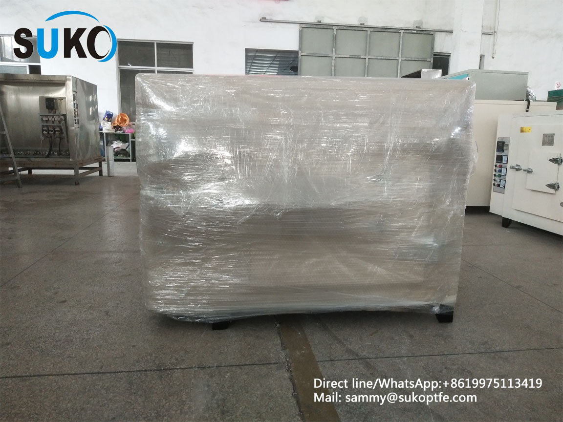
Belgian customers have received our customized ovens.


Belgian customers have received our customized ovens. Our customers are very positive about our products and services. We can produce various types of ovens and sintering furnaces such as high temperature ovens, PTFE ovens, natural gas sintering furnaces, vacuum sintering. Furnace, stainless steel oven, PTFE rotary sintering furnace, trailer type sintering furnace, etc. Our oven has double safety system, program control, automatic temperature rise and cooling, can set 56 section temperature, with time control and ultra-high temperature double safety protection, good insulation performance, uniform furnace temperature, sintering curve, timing value and temperature can be set. value. The working temperature error in the furnace is ±1 °C, and there is no error within 1000 hours of operation. The inside of the hearth and the turntable made of stainless steel will not rust. 2019 has arrived, and in the new year we will be happy to provide our customers with the best products and the best service.
SUNKOO Machine Tech Co.,Ltd
Company website:www.sukoptfe.com

Wednesday, December 19, 2018

Extrusion of polymers


Extrusion is a process of manufacturing long products of constant cross-section (rods, sheets, pipes, films, wire insulation coating) forcing soften polymer through a die with an opening.
Polymer material in form of pellets is fed into an extruder through a hopper. The material is then conveyed forward by a feeding screw and forced through a die, converting to continuous polymer product.
Heating elements, placed over the barrel, soften and melt the polymer. The temperature of the material is controlled by thermocouples.
The product going out of the die is cooled by blown air or in water bath.
Extrusion of polymers (in contrast to extrusion of metals) is continuous process lasting as long as raw pellets are supplied.
Extrusion is used mainly for Thermoplastics, but Elastomers and Thermosets are also may be extruded. In this case cross-linking forms during heating and melting of the material in the extruder.
The thermoplastic extruded products may be further formed by the Thermoforming method.

Saturday, December 15, 2018

Six PTFE special ovens ordered by Belgian customers have been produced and ready for shipment.

The ovens have been produced and ready for delivery. Our company can produce various types of ovens and sintering furnaces such as high temperature oven, PTFE oven, natural gas sintering furnace, vacuum sintering furnace, stainless steel oven, PTFE rotary sintering furnace, trailer type sintering furnace and so on. Our oven has double safety system, program control, automatic temperature rise and cooling, can set 56 section temperature, with time control and ultra-high temperature double safety protection, good insulation performance, uniform furnace temperature, sintering curve, timing value and temperature can be set. value. The working temperature error in the furnace is ±1 °C, and there is no error within 1000 hours of operation. The inside of the hearth and the turntable made of stainless steel will not rust.